Chroma Memory Extension: The 1600 Programs Chroma
By Michael Röpsch [21030816]In 1995 I built a Memory Extension to 32 banks resulting in 1600 programs. It's a simple piggy-back circuit using three TC55257 instead of the six original SRAM chips. The five address lines added are still controlled by some external switches because it would break my heart to modify the Chroma's beauty.
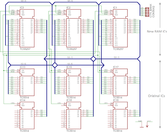
The Chroma Memory Extension CME is a very, very simple Plug'n'Play board which is mounted into the sockets of the original RAM ICs. In the schematic the IC13..18 are the original parts (although labeled here as TC5514); they are only used as placeholders for the board layout. The couples IC13,14, IC15,16 and IC17,18 have their correspondent IC1, IC2 and IC3 (TC55257 - 32kx8 SRAM) combining to 8bit. The battery backup circuit of the computer board is still in use, also the blocking capacitors. No other circuits integrated. As seen in the schematic I decided to swap address lines and on the other side data lines to simplify the single-sided board layout.
Fig. 1 CME Schematic
On the board layout the original ICs are mirrored and replaced with pin connectors, which are directly slotted in the RAM sockets on the Chroma's computer board mounting the CME top-down.
Fig.2 CME board print layout
Fig.3 CME board place plan
The five additional address lines are led out of the Chroma and controlled by external switches - but 'til now as a interim solution... better not to talk about! (The reason why: I wanted to have a dial for bank loading and a toggle switch for two preloaded bank numbers to avoid 'heavy' scrolling. To manage 5 bit in standard TTL or CMOS in a small circuit is not a funny job, and I had no prommer - so the times were passing...)

Pic. 1 CME mounted

Pic. 2 CME mounted (detail)
You can also download this article as a PDF: Chroma Memory Extension.pdf, 575K ![]()


