Interface Manual: Hardware Requirements
This section describes the circuits needed to interface a computer to a Chroma. It is assumed that the reader is reasonably familiar with the bus structure of his own computer, and what is shown here will have to be modified accordingly. In particular, details of address decoding, bus acknowledge and interrupt control are not shown.
Minimal Interface
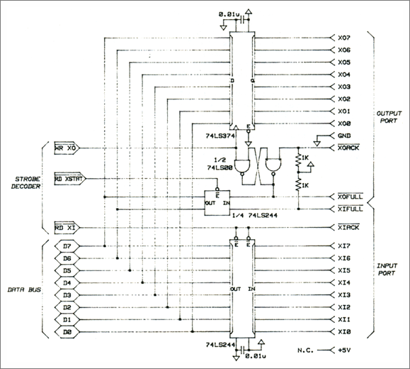
At the very least, one must have an 8-bit latch driving the output lines that can be written into, an 8-bit tri-state driver sensing the input lines that can be read from, and a set/reset flip-flop associated with the output lines that maintains the status of the output port. (The other end of the interface maintains the status of the input port.) In addition, there must be a way of sensing the status of the two ports. This is shown in Fig. 5-1.
It is assumed here that the bus cycle strobe, read and write signals and address are all decoded to provide individual active-low strobes to all circuits that require them, that acknowledgement is taken care of elsewhere (no wait states should be needed), and that the data bus is an 8-bit positive logic bus. Note that the XOACK (External Output Acknowledge) and XIFULL (External Input Full) lines are resistor terminated. This is because the Chroma drives these lines with open collectors.
Fig. 5-1 Minimal Interface
The bus drivers shown here are LS TTL devices, as they are probably the cheapest kind. For better noise immunity, HCT series CMOS can be used for the outputs. CMOS devices should never be used for inputs, though, as CMOS gates are prone to damage when connected to the outside world.
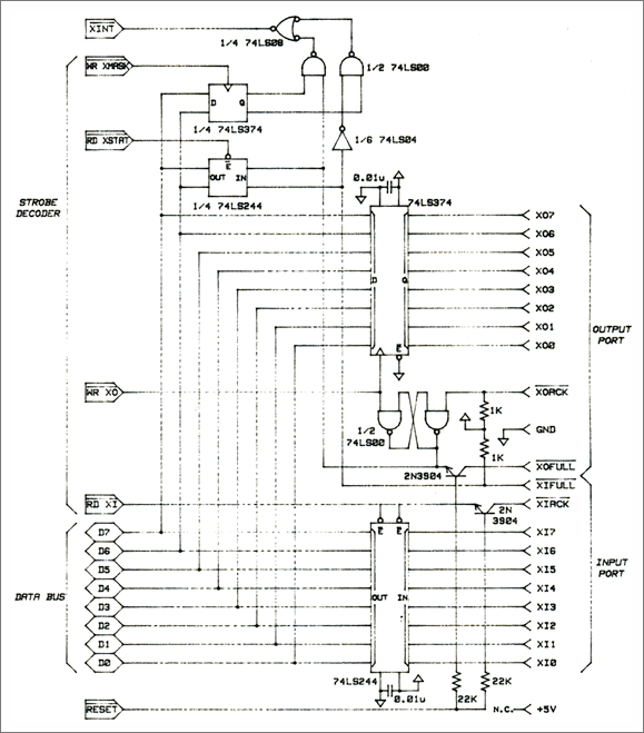
The XIACK (External Input Acknowledge) and XOFULL (External Output Full) lines are drive through transistors so that these outputs will not be pulled down when the computer is turned off. Without these transistors, turning off the computer would continuously interrupt the Chroma. Since these outputs are open collectors, the corresponding inputs XOACK (External Output Acknowledge) and XIFULL (External Input Full) lines must be resistor terminated.
Interrupt Driven System
The status of each port can be used to generate an interrupt. The input port should be capable of generating an interrupt when it is full, and the output port should be capable of generating an interrupt when it is empty. In addition, each interrupt should be independently maskable. If a multi-level interrupt structure already exists in your system, you will only need to connect the status lines (inverting one of them) to two interrupt lines. Otherwise, a 2-bit output port must be provided to hold the interrupt mask bits, and some gates must be provided to combine everything into one interrupt line. This is shown in Fig. 5-2. The circuit shown maintains the interrupt until the condition causing it is removed. Some systems will require an open collector interrupt signal.
Fig. 5-2 Interrupt Driven Interface
Connecting to the Chroma
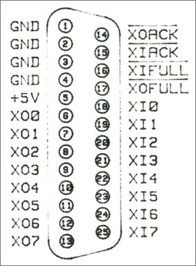
The physical interconnection to the Chroma is through the 25-pin D-type connector on its rear panel. Figure 5-3 shows the pin-out of the connector. Note, however that the names of the connections shown in this diagram are from the Chroma's point of view. That is, the lines that are associated with the "output" port deal with information flowing out of the Chroma, and the lines that are associated with the "input" port deal with information flowing into the Chroma.

Note: this pinout should be used at the computer's end of the interface, along with the "crossover" type cable.
Fig. 5-3 Chroma D-connector Pin-out
Obviously, the Chroma's output lines must connect to the computer's input lines and vice versa. There are two ways to do this. The preferred approach is to use a "crossover" cable that connects the XO lines at one end to the XI lines at the other end. This guarantees that all devices that have Chroma Interfaces have the same pinout, and can be connected with one kind of cable. Rhodes sells a sturdy shielded crossover cable, with molded plugs at each end, that was designed for this purpose.
If you wish to use an inexpensive off-the-shelf ribbon cable, you must assign pin numbers at the computer's end of the interface according to the scheme in figure 5-4. This will connect the XO lines at one end to the XI lines at the other. If you choose this approach, you will have created a second "sex" of device, possibly causing confusion if you have more than two devices using the Chroma Interface.

Note: This pinout may be used at the computer's end if an off-the-shelf ribbon cable is to be used. See text.
Fig. 5-4 Complementary Pin-out


