

Service Manual: Disassembly
Access to the Chroma for troubleshooting is quite straightforward. Figure 3-1 shows an exploded view of the screws holding the top cover in place. Remove the nine black screws (1-9) from the back and the four bronze screws (11-14) from the wood rail above the control panel. Do not remove screw 10 until you gently remove the cover. Screw 10 holds a green ground strap under a nut inside the cover (see Figure 3-2) which may be removed after you lift off the cover.
Remove four screws (15-18) from the sloping panel (Figure 3-2). The panel is pivoted and may be raised up and back as shown in Figure 3-3.
As can be seen from Figure 3-3, most electronic boards are easily accessible with the Chroma open. Notice the order of the Dual Channel Boards. They are numbered from left to right in a "U" shaped configuration, while facing the keyboard. These numbers are silkscreened on the Channel Mother Board (not shown) into which the Dual Channel Boards are plugged. Any of these boards may be replaced without the need for soldering. Where a cable terminates on one board with solder joints, the other end of the same cable will have connectors. Visual examination of the assembly of these boards will reveal the procedures necessary for successful disassembly.
It is not so obvious how the Power Supply may be removed. Ten screws up from underneath the Chroma secure the supply. All ten (see Figure 3-4) should be removed from the bottom to detach the supply. The screws are threaded into standoffs holding the suply off the bed of the Chroma. The supply and rear panel are removed in one piece. When pulling the connectors from J1, J2 and J3, notice they are keyed identically and can be inadvertently connected incorrectly when re-installed. Refer to the Connection Diagram (Figure 3-5) and go by the colors of the wires.

Fig. 3-1

Fig. 3-2

Fig. 3-3

Fig. 3-4
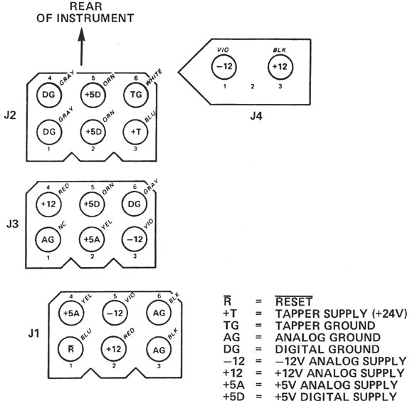
Fig. 3-5